Edges and isocurves
What makes a CAD model read as a CAD model is its lines: the edges where faces meet, the curves that were never a solid, the rulings across a surface. They are exact curves in the file, and the plugin draws them as lines rather than as thin geometry.
Edges, curves, isocurves
| Kind | What it is |
|---|---|
| Edges | Where two faces of a body meet. The outline of the part as a machinist would draw it. |
| Curves | Lines, arcs and splines in the file that bound nothing: centrelines, sections, sketch geometry that was never extruded. |
| Isocurves | The lines of constant u and v across each surface — how most CAD viewers shade a surface. The most expensive of the three by a long way: they cover every face rather than only its rim. |
Whether each family is built is decided at load (Load Edges, Load Curves, Load Isocurves, all on). Whether each is drawn is a question the render thread asks every frame, so a kind can be shown and hidden at a keypress — through Set Draw Curve Kind, which pushes the change; assigning the property alone leaves the render thread drawing what it drew before.
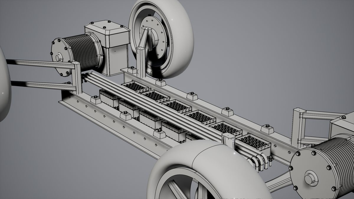
The surface, ruled
Isocurves show the shape of a face rather than its boundary, and they are what makes a surface model look like a surface model.
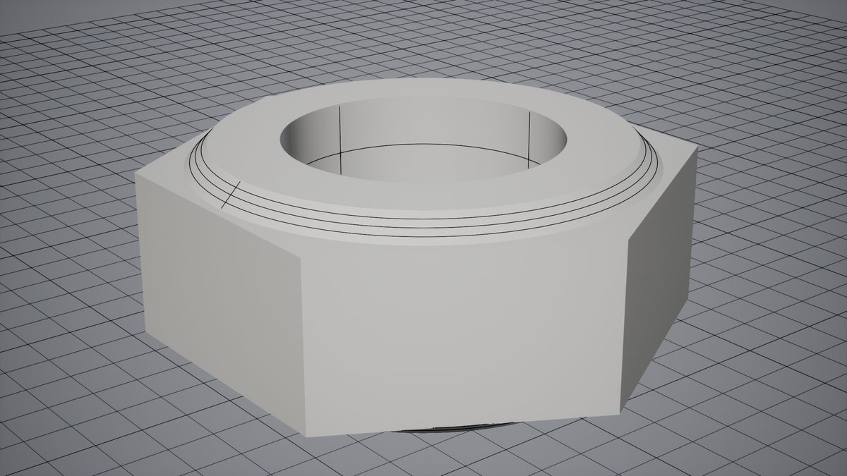
The x-ray wireframe
Draw Lines On Top draws every line over the model, the ones behind it included — worth having when the shape of an assembly matters more than which face of it is nearer.
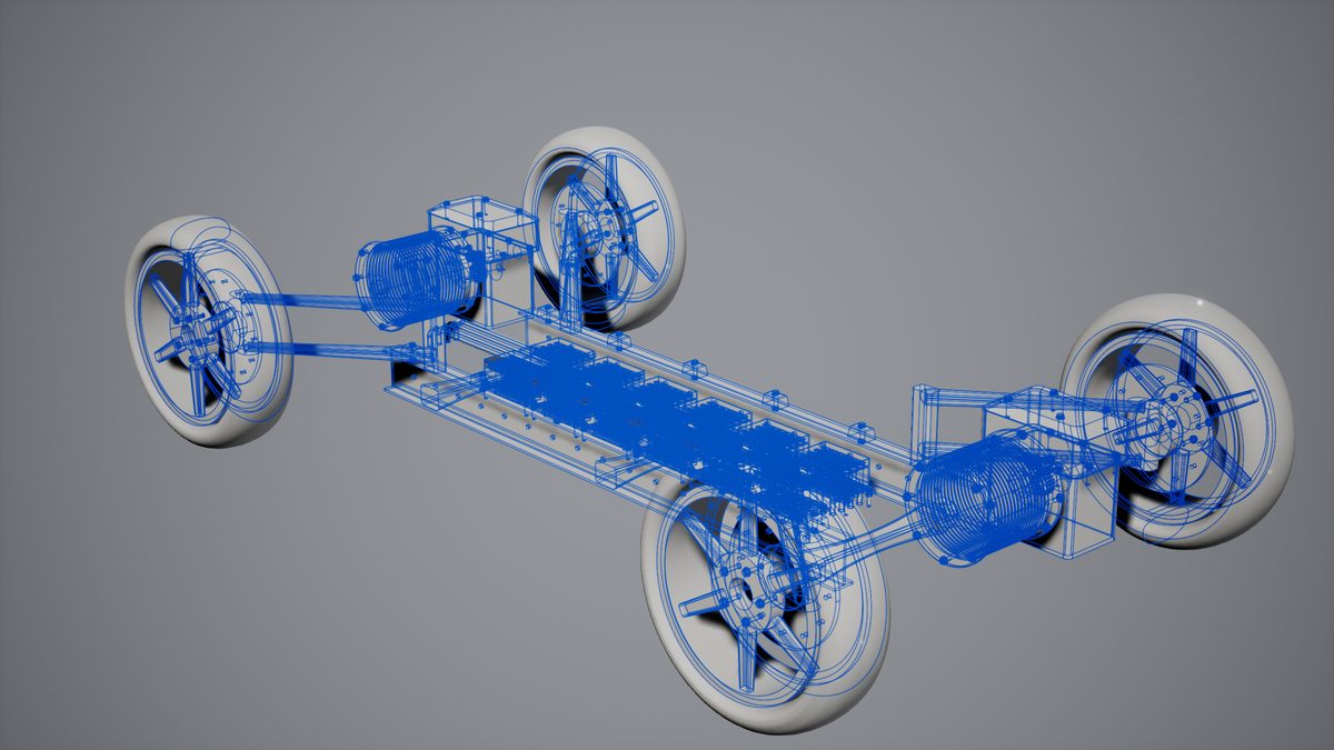
Off — the default — an edge on the far side of a solid is hidden by it, which is what a solid looks like. The test that hides them is done before temporal anti-aliasing, against a depth buffer drawn with the same sub-pixel jitter as the lines, so it is exact. A document with nothing of its own in the depth buffer, or with free curves, has its lines drawn after anti-aliasing instead, where the test reads the depth around the pixel and can flicker along silhouettes under TAA or TSR; r.Cadaclysm.LineOcclusionBias and LineOcclusionSlopeMax tune it. r.Cadaclysm.LinesAfterTonemap 1 draws every document's lines that way. Lines of your own from a UCadaclysmLineComponent — a floor grid, an axis — write their own depth and are drawn before anti-aliasing too, unless they are drawn on top. Drawn there, lines go through the post-process chain like the rest of the scene: their colour is converted so it shows as given, but bloom spreads bright surroundings over them, so a viewer with a light background wants bloom off.
Colour and weight
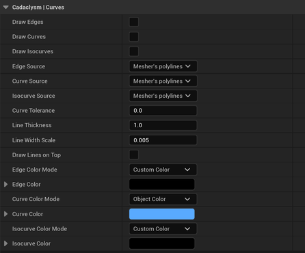
Document component: which kinds draw, where each comes from, how thick, and in what colour.Each kind takes its colour from its own pair of settings: a mode — the part's own colour, or one custom colour for the whole kind — and the colour to use. Ink for edges, the part's colour for free curves is a reasonable default and is what the plugin starts with.
Line Thickness is in pixels and is live: it is a number the shader reads, so changing it rebuilds nothing. Line Width Scale lets a line have a worth in world units as well, so lines thin out as the camera pulls away instead of keeping their weight; zero turns that off and leaves the pixel width alone.
One part's lines can be picked out of the rest with Set Node Line Highlight — a colour and a thickness for one part and one kind, given back with Clear Node Line Highlight. That is what a selection outline is made of; see picking.
Where a line comes from
Each kind is built from one of three descriptions, chosen by Edge Source, Curve Source and Isocurve Source. The right answer differs by kind, which is why there are three.
| Source | What it draws | Cost |
|---|---|---|
| Mesher's polylines | The chords the mesher walked. They lie exactly on the triangles, so nothing z-fights against a meshed part. | Free where the part is meshed anyway. The default. |
| Exact curves | The file's own curves, flattened to a tolerance you set (Curve Tolerance). A silhouette that never wobbles off the true edge. | Meshes the part: the reader builds triangles and exact edges together. |
| Trims | The trim loops of the part's surfaces, lying on the surfaces themselves. | The only one that does not mesh the part — and the one to use with the surface component. |
The plugin does not let this go wrong quietly: a part drawn from its surfaces is lined from its trims whatever the property says, because building an exact edge for it would rebuild every triangle the surface path had just been careful to skip. Against a meshed part, trims z-fight and the polylines are the right choice. Only the caller knows which is on screen, which is why this is a choice and not a default.