Draw a building, export IFC
The BIM editor draws a building the way an architect thinks of one: walls with real layers, doors and windows that sit in them, floors and levels. You draw on the plan at the left; the model at the right is built by the kernel from exact solids, every wall cut where its openings are and trimmed where it meets another. When you are done, the building leaves as IFC, the format other BIM tools read. The kernel runs in your browser, and nothing is uploaded.
This page starts from the sample house and then draws on it. Open the editor with the sample house beside this page and follow along.
The sample house
The editor starts on an empty project with one level, Ground. Open the File menu at the left of the toolbar and press Sample house (the link above already did): a two-storey house of 10 × 8 m, with brick-faced exterior walls, a partition on each floor, two doors downstairs, nine windows, a concrete slab under each floor, a U stair up from the kitchen and dimensions on the ground plan and in a section through the stair. Pressing it over a drawing asks first, since the sample replaces what is there.
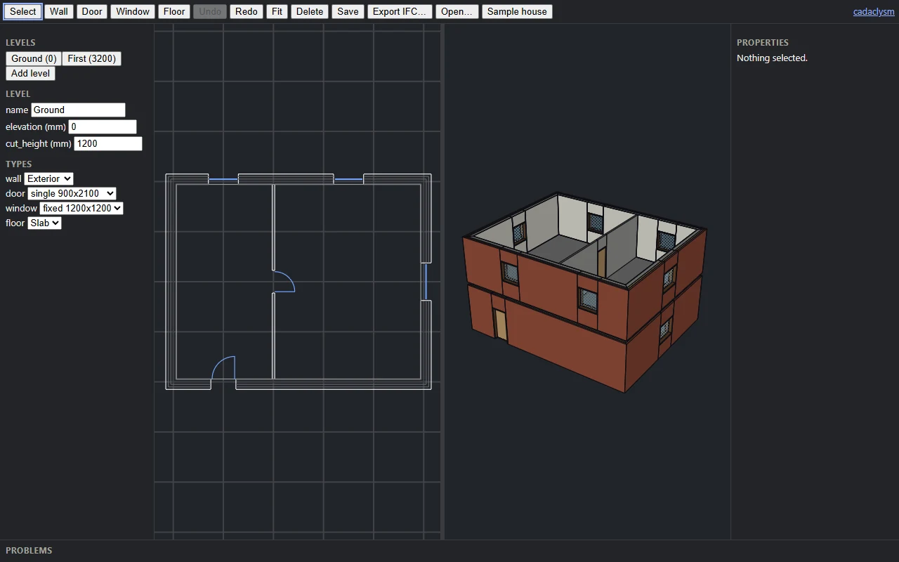
The plan is the active level cut at its cut height, 1200 mm, as drawings are: walls show their layers, doors their swing, windows their glass line. The model shows every level at once; drag in it to turn it, or click a face of the cube in its bottom-right corner to look square at that side (TOP looks straight down). Fit frames both views on the building, and the bar between them drags to give either more room (it also moves with the arrow keys).
Levels and types
The project tree on the left holds the whole building in four folds. Under Levels, a click switches the plan between storeys: press First (3200) to draw upstairs. The first floor sits at 3200 mm, so its 200 mm slab rests on the ground floor's 3000 mm walls. Under the levels the active level's name, elevation and cut height can be changed; Add level adds one 3000 mm above the top one. Schedules lists the building's schedules, Types its types by category (a tick marks the type a tool's next element takes), and the last fold, named after the active level, its walls, doors, windows, floors, rooms, columns, beams, stairs and roofs, each kind with its count. A click on an element or a type selects it; the field at the top filters every fold by name.
Pick a tool and the bar under the toolbar shows what it does next: the level it draws on, the Type its next element is made of, with one line on what that type is, and the next click in words. For a wall that is Exterior (4 layers, 415 mm of brick, insulation, block and plaster) or Partition (100 mm of block); each tool keeps its own type when you switch away and back. The type is a separate thing the element points to, as in IFC: every wall of a type shares its layers.
Draw
On the ground floor, pick Wall and the Partition type in the tool bar, then split the big right-hand room: click on the middle partition a little below its door, then on the outer wall straight across to the right, below its window. The wall goes in and joins both, and the model shows it trimmed into them. Clicks catch the ends and the middle lines of walls already there, so walls meet exactly. Each click starts the next wall from the last point; Esc or Enter ends the run.
Door and Window go in a wall: move over one and the opening's width is previewed along it, then click. Give your new partition a door. An opening that would overlap another is refused with the reason, and nothing changes. Floor takes either the walls that close a room, clicked in turn and closed by clicking the first again, or a sketched outline: click its corners on empty plan and press Enter.
Rooms
Pick Room and click inside a space the walls close: the room takes the walls round it, gets the next number and a tag on the plan with its number, name and area in m². The room is as tall as the gap to the next level, or 2.7 m on the top one (in any unit the document uses). With Select, click the tag to select the room, click it again to pick it up, and click where the room is to be looked for instead, and change its name and number in the Properties panel along with its area, perimeter and volume.
A door or a window does not split a room: the wall stays a wall across its opening, so a room ends at walls, not at doors. If walls are later moved or removed so that the room no longer has a closed outline, or its point ends up inside a wall, the tag turns to a warning and the Problems list says why; clicking clear space with the Room tool outside any walls is refused the same way.
Columns and beams
With Column or Beam picked, the Type in the tool bar chooses the section a new member takes: Column 300 × 300 and Beam 250 × 450 in concrete, or the steel HEA 200 (a beam's type list offers only the rectangular and I sections, not a round one). Pick Column and click: a column goes in at the point, caught on wall ends, wall middle lines and other columns' centres, from the active level up to the next one (3 m tall on the top level). Pick Beam and click its two ends: they catch column centres and wall ends, its top sits at the next level up (2.7 m above the top level), and each click starts the next beam from the last point until Esc or Enter. The sample's carport, beside the house, is two columns and a beam into its right-hand wall.
Members win: a column cuts the walls, floors and beams it passes through, and a beam the walls and floors, so nothing is counted twice and every volume stays exact. In the plan a column at the cut height is drawn cut and filled in its material's colour, with the wall's lines stopping at its faces; a beam above the cut is drawn dashed, one below in grey. With Select, click a column or a beam to see its levels, offsets, rotation or ends and its length, areas and volumes in the Properties panel; Edit type opens its section's dimensions. Click a selected column again to pick it up and click where it goes; a selected beam's ends drag like a wall's; a box select takes columns by their centre and beams by both ends. A column from another level that runs up through the cut height is drawn on this level's plan too, and a click there selects it. Set a member's top level to none and it keeps its height; move a wall or column to a level its top level is not above, and its top moves to the next level up (or it keeps its height on the top level). A column or beam that would sit in a door or window, or a beam whose columns would swallow it whole, is refused with the reason. The columns and beams schedules list them with their size, length and volumes, and the IFC export writes them as columns and beams with their own types and quantities.
Stairs
Pick Stair to draw one. The tool bar sets its Type (the first stair brings Concrete stair: risers of 180 mm at most and a 280 mm going), its Width, what a corner becomes (a Landing or Winders), a rail on either side, and the Mode. In Path mode, click along the walk line, the stair's centre line, from its foot: each click adds a corner, and the preview draws every tread to the cursor and says how many risers the stair takes and how many fall on the segment you are drawing. Press Enter, or click the last point again, to finish: the last click sets the last flight's direction, and the steps set its length. In Spiral mode, click the centre and then the start; the steps decide how far it turns, counter-clockwise unless Clockwise is ticked. A stair rises from the active level to the next one up, with as few risers as keep each one under the type's largest, so a level moved up or down re-steps every stair it bounds.
A stair cuts the floors it rises through wherever it needs headroom. The plan draws its risers below the cut height solid, a break line, the rest dashed and an arrow from its foot marked UP; on the level above it draws the part you see through the opening, marked DN. The sample's U stair runs up the kitchen's west wall to a half landing and back. Select it to see its risers, riser height, going and pitch; switch a corner between landing and winders in the Corners table, or give a segment a bulge in the Segments table to curve it (0 is straight). Sections cut stairs and fill them by material, and the IFC export writes each stair with its flights, landings and rails.
Schedules
The view bar under the viewports says what they show. Schedules puts the schedules beside the plan, where the 3D view was, and 3D brings the 3D view back; One lets the view you pick fill the whole area, and Two puts the plan back beside it. Other level puts a second level's plan beside the active one, the level above it to begin with; the box over its corner picks another. The two plans pan and zoom together, whichever you move, so a wall upstairs lines up with the one under it. You draw on the active level's plan only: click a level in the project tree to swap. The sample house comes with four: a Door schedule, grouped by type with totals, a Room schedule, one row per room with the area and volume added up, and a Column schedule and a Beam schedule for the carport, with each member's size, length and volume. The list on the left picks which one the table shows; a schedule picked in the project tree opens the Schedules view on it. To make another, choose a category (doors, windows, walls, floors, rooms, columns or beams) beside New schedule and press it: it starts with four columns and one row per element of that kind.
The toolbar over the table holds Name, Columns (tick the ones to show; the arrows move a ticked column left or right), Add filter (pick a column, a comparison and a value; lengths are typed in mm, areas in m² and volumes in m³, whatever unit the document uses), Group by and Totals, which adds a total row under each group and a grand total for the columns that can be added up. An empty cell is skipped by the totals. Click a column header to sort by it, and click it again to sort the other way. Clicking a row selects its element, highlighted in the plan and the model; if it is on another level, that level becomes the active one. A room the walls no longer close shows as a warning row with no figures instead of breaking the table. CSV downloads the table as it is shown, and Delete schedule removes it.
A schedule is part of the model: it is saved in building.json, every change to one is a step of Undo and Redo like any other, and its figures follow the drawing as you move walls. Schedules are not written to the IFC file.
Sections
A section cuts the building along a line and shows what the cut crosses and what lies beyond it. Pick Section in the toolbar's View group and click the line's two ends on the plan; the section looks to the left of the way you drew it, and the tool bar's Flip turns it round before you draw, Depth sets how far beyond the line it sees (10000 mm at first). Its mark, a dash-dot line with an arrow at each end, shows on every level's plan; with Select, click it to see the section's name, ends and depth in the Properties panel, where Flip turns it round and Open shows it.
A section opens beside the plan, where the 3D view was (or fills the area in One); Sections in the project tree and the Section tab in the view bar open it too. The walls, floors, columns, beams and roofs the line cuts are filled in their materials' colours, their layers drawn as in the plan, and everything beyond them up to the depth is drawn with its hidden lines removed; each level is a dash-dot line with its name and elevation. Click an element in the section to select it, as in the plan. Click a level line to pick it up and click again where it goes: the level moves, and every element on it follows. The drawing follows every change you make. Download SVG writes it at the scale beside it (1:50, 1:100 or 1:200), with pens of 0.5 mm for the cut, 0.25 mm between layers and 0.18 mm for what lies beyond. An element whose body cannot be built is left out and named in the status line.
Elevations
An elevation shows the building from outside: what lies beyond its line, with hidden lines removed, and nothing cut. Add elevations in the toolbar's View group places four round the building, North, South, East and West (north is up the plan), each 3 m outside it and looking at it; run it again and any of them you moved goes back to its place. Pick Elevation and click a line's two ends to place another, looking to the left of the way you drew it; Flip and Depth in the tool bar work as for sections. Its mark is a circle with an arrow toward what it sees; with Select, click it to see its line and its name, ends and depth in the Properties panel, with Flip and Open.
Elevations in the project tree opens one where a section opens. The building's outline against the sky and the ground is drawn heavier, and a ground line runs along the lowest level; each level is a dash-dot line with its name and elevation. Select an element or move a level there as in a section. An elevation whose line you moved inside the building still cuts nothing: it shows what lies beyond the line. Download SVG writes it with pens of 0.7 mm for the ground, 0.5 mm for the outline and 0.18 mm for the rest.
Dimensions
Pick Dimension in the toolbar's View group to measure the drawing, in the plan or in an open section or elevation. The tool bar's Style chooses what it draws. A Linear chain: click each face, centre or end in turn (the reference under the pointer is highlighted and named in the bar), press Enter or click the last one again, then click where the line goes; the preview follows the pointer and says the lengths. Direction keeps the chain horizontal, vertical or square to the first face; Auto picks one from the first two clicks. An Angular dimension takes two faces or lines and a click for its arc, a Radial one an arc and a click for its leader, and a Height mark, in a section or an elevation, a level, a sill, a head, a slab or a ridge and a click for the mark. Esc starts over.
A dimension follows what it measures: move a wall and its chain re-labels; delete a door and its witness line drops and the chain closes up, with the lost reference named in the Properties panel. Click a dimension to select it, and click its line again to pick it up and move it. Properties lists its references, each with Remove; Add point adds the next ones you click to the chain. The project tree lists each view's dimensions under it, and the Project fold sets how every dimension writes its numbers: the Dimension unit (millimetres, centimetres, metres, or feet and inches), the Decimals and the Fraction of an inch. The sample house has a chain along its south and east sides and a section through the stair with its levels marked. Dimensions are drawn in the section's Download SVG, black at 0.18 mm.
Select and change
With Select, click an element to see it in the Properties panel. Its type comes first, with a drawing of its layers or section, its size and Edit type; a different type picked there changes the element. Under it the fields are grouped as Constraints (levels, offsets, height), Geometry (a wall's ends, an opening's position along its wall) and Quantities, and a wall lists the joins it takes part in: click one to select it, and Delete join removes it. Type a value and press Enter; a value the kernel cannot build is refused under its field. Click a selected wall's end to pick it up and click where it goes, and its joins follow. Click empty plan, then click the opposite corner, to box-select (rooms count by their point); clicking a room that is already selected selects the floor under that point; Delete removes the selection, and a wall takes its openings with it.
Every change is one step of Undo and Redo (Ctrl+Z, Ctrl+Shift+Z). Anything the kernel cannot build is counted in the status line at the bottom (No problems, or how many); click the count to open the Problems list, and click a row to select the element it names.
The Code tab
Beside the Properties tab in the right-hand column, the Code tab says what your last edit did in a sentence or two (the wall added or moved, what it now meets or no longer meets, which rooms and plans were recomputed and which bodies are queued for the kernel to rebuild) and shows the kernel calls that built the solids it changed, under a Python and a Rust tab. Every solid of a building is one outline extruded between two heights, so the code is a Profile (a polygon, or a path of lines and arcs for a round column, with any holes) and Solid.extrude_between, with the very numbers the editor built it from, in the document's unit. The element you edited comes first; other elements the edit rebuilt (a wall a new column now cuts) are listed below, folded. An edit that builds no solid, such as renaming a level, says so. With something selected it shows the calls that build that element's solids now.
Copy script and Download give the whole building as a program in the chosen language: it builds every element's solids with those same calls and writes them to building.step. The Python runs with the SDK's cadaclysm_blacksmith module; the Rust needs only the cadaclysm-sdk crate. It is written from the building as it is now, not from its history. The Properties tab puts it away again, and the editor remembers which tab you chose. The status line at the bottom of the window repeats the last edit in words whichever tab shows; click it to open the Code tab.
Save and open
Save in the File menu (Ctrl+S) writes the building as a cadaclysm document, building.json: the first save asks where, the next ones write back to the same file. Open (Ctrl+O) reads one back. Browsers without file pickers download the file and open it from a file input instead. The editor keeps none of your drawing between visits, so save before you close the tab. The same document opens in the Python SDK.
Export IFC
Press Export IFC… in the File menu and choose a schema and a geometry, then Export: the building downloads as building.ifc, with a storey per level, each wall, door, window and floor under its storey, its type and its layered materials; each room is written as a space with its area, perimeter, height and volume, and every element carries its base quantities, measured from the building's own dimensions rather than from the triangles. IFC4 is the current schema; IFC2x3 is the older one many tools still expect.
Parametric writes each wall as its profile extruded to its height, with every opening a void cut from it, so the receiving tool can still edit them. A wall that a crossing join cuts in two is written as one wall of two extruded pieces. Exact writes the solids the kernel built, as triangles. Anything the export cannot write (an element with a problem, say) is listed in the dialog instead of a file, and clicking a row selects that element.
Sheets
A sheet is a page of drawings ready to print: plans, sections, elevations and schedules placed at a scale on ISO or ANSI paper, under a title block filled in from the project and the sheet. Open the Sheets tab under the views and press New sheet: an A1 landscape sheet appears, numbered after the last one (A-101 first). Pick a view in Place, press the button beside it and click the paper where its centre goes; plans, sections and elevations go down at 1:100, schedules as a table. Click a view on the paper to select it, click it again to pick it up and click where it goes; Escape puts it back. Properties set its scale, its title and its crop — Crop to the plan view keeps just what the plan showing beside the sheet shows, so show that plan's level in the plan pane first — and the sheet's paper, orientation and title block. A view that runs off the frame or over the title block is outlined in red, its warning in Properties. Download SVG and Download PDF write the sheet; Download set (PDF) writes every sheet in one PDF, in number order, a bookmark a page. The project's name, number, client, address and author are in the tree's Project fold. The sample house comes with sheet A-101, its two floor plans and its door schedule.
A 3D view goes on a sheet too. In the 3D view, Save camera keeps the view as “3D view 1” (then 2, 3 and so on), listed under Cameras in the tree. Place it like any other view and it goes down as a line drawing: only the lines you can see, with hidden lines left out and joined faces drawn as one surface, so a wall’s layers and a floor flush with it show no joint. A camera is either perspective or parallel (its Projection in Properties). A perspective one fills its box, 120 mm wide at the 3D view’s shape at first, with its width and height in Properties; a parallel one is drawn at a true scale, 1:100 at first, with the scale under its title and no size to set. Switching the projection keeps the other one’s setting for when you switch back. Style in the viewport’s Properties switches a view to the rendered Picture instead, which is rendered again after each edit and at 200 dpi in the downloads. The sample’s sheet A-201 shows the section, the south elevation, a perspective view from the south-east and an axonometric from the same side at 1:100.
What the editor does not do yet
- Walls, doors, windows, floors, rooms, columns, beams, roofs, stairs and levels. Roofs show in 3D and in the IFC export, not on plans or in schedules. A roof has no holes: a pick inside a building round a courtyard roofs its whole outline, courtyard included, so draw each wing's roof instead. Stairs are solid flights on a sloping underside, with their rails as part of the stair: no stringers, open risers or stair schedules, and a spiral turns less than a full circle. No curtain walls yet.
- Straight walls. No curved walls, and the built-in types are the only types.
- Export only. The editor writes IFC; it does not open IFC files.
- One person at a time. There is no shared editing yet.