Lines of your own
A CAD scene is more than the file it opened: a floor to judge size against, axes to say which way is up, a box round the part you picked, the path something will travel. UCadaclysmLineComponent draws them with the renderer that draws a model’s edges, so they look like the model’s lines and behave like them.
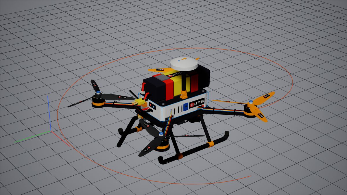
The edge renderer, for anything that is not a document
Every line it draws is a width in pixels at any distance, anti-aliased, and drawn inside temporal anti-aliasing with its own depth and motion, so it neither flickers on a still camera nor trails behind a moving one. Unreal’s debug lines give none of that: their width is in world units, a hairline on a bolt and a slab across a site.
By default the scene hides them where something stands in front, which is what a floor or a box should do. Draw Lines on Top draws them over everything instead: the choice for a gizmo, a measurement, or anything that is about the scene rather than in it.
It is not a document: it has no nodes, no tree and no picking, only segments. Put it on any actor, as many as you need.
Points in pairs, colours in runs
Set Lines takes two arrays. Points holds two points per segment, start then end, in the component’s own space. Spans says which segments are drawn in which colour: each span is a run of consecutive segments, FirstSegment and SegmentCount, in one colour. A run is one draw, so sort lines that share a colour together.
Set Lines rebuilds the component’s buffer. To move, rotate or scale lines that have not changed, move the component instead, which costs nothing. Set Line Thickness changes the width without rebuilding either. In C++ the points are FVector3f; Blueprint’s Set Lines takes ordinary vectors.
A floor grid
A ruled floor under a model, every tenth line darker: two runs, one per colour. The step here is 10 cm; choose one that suits what stands on it.
UCadaclysmLineComponent* Grid = NewObject<UCadaclysmLineComponent>(this);
Grid->SetupAttachment(GetRootComponent());
Grid->RegisterComponent();

const int32 Half = 40;          // lines each side of the middle
const float Step = 10.0f;       // centimetres between lines
const float Reach = Half * Step;
TArray<FVector3f> Points;
TArray<FCadaclysmLineSpan> Spans;
for (int32 Major = 0; Major < 2; ++Major)
{
    FCadaclysmLineSpan Span;
    Span.FirstSegment = Points.Num() / 2;
    Span.Color = Major ? FLinearColor(0.28f, 0.30f, 0.34f) : FLinearColor(0.42f, 0.44f, 0.48f);
    for (int32 I = -Half; I <= Half; ++I)
    {
        if ((I % 10 == 0) != (Major == 1))
        {
            continue;
        }
        const float At = I * Step;
        Points.Add(FVector3f(At, -Reach, 0.0f));
        Points.Add(FVector3f(At, Reach, 0.0f));
        Points.Add(FVector3f(-Reach, At, 0.0f));
        Points.Add(FVector3f(Reach, At, 0.0f));
    }
    Span.SegmentCount = Points.Num() / 2 - Span.FirstSegment;
    Spans.Add(Span);
}
Grid->SetLineThickness(1.5f);
Grid->SetLines(Points, Spans);An axis gizmo
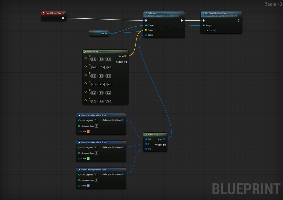
Three segments, and three spans so each axis has its own colour, drawn on top so the model never hides them.
UCadaclysmLineComponent* Axes = NewObject<UCadaclysmLineComponent>(this);
Axes->SetupAttachment(GetRootComponent());
Axes->RegisterComponent();

const float Arm = 50.0f;
const TArray<FVector3f> Points = {
    FVector3f::ZeroVector, FVector3f(Arm, 0.0f, 0.0f),
    FVector3f::ZeroVector, FVector3f(0.0f, Arm, 0.0f),
    FVector3f::ZeroVector, FVector3f(0.0f, 0.0f, Arm) };
const FLinearColor Colours[3] = {
    FLinearColor(0.9f, 0.15f, 0.1f), FLinearColor(0.2f, 0.75f, 0.2f), FLinearColor(0.15f, 0.35f, 0.95f) };
TArray<FCadaclysmLineSpan> Spans;
for (int32 Axis = 0; Axis < 3; ++Axis)
{
    FCadaclysmLineSpan Span;
    Span.FirstSegment = Axis;
    Span.SegmentCount = 1;
    Span.Color = Colours[Axis];
    Spans.Add(Span);
}
Axes->SetLineThickness(3.0f);
Axes->SetDrawLinesOnTop(true);
Axes->SetLines(Points, Spans);
The same in Blueprint: add a Cadaclysm Line component, then call Set Lines with a Make Array of points and one of spans.
A box round a part
The twelve edges of a part’s bounds, from Get Node Bounds, to show what was picked or what a query found. Drawn with the scene’s depth, so the part hides the edges behind it.
// Node: the part, from Get Hit Node or Query Nodes.
const FBox Bounds = Document->GetNodeBounds(Node).TransformBy(Document->GetComponentTransform());
const FVector Lo = Bounds.Min - Bounds.GetCenter();
const FVector Hi = Bounds.Max - Bounds.GetCenter();
const FVector3f Corner[8] = {
    FVector3f(Lo.X, Lo.Y, Lo.Z), FVector3f(Hi.X, Lo.Y, Lo.Z), FVector3f(Hi.X, Hi.Y, Lo.Z), FVector3f(Lo.X, Hi.Y, Lo.Z),
    FVector3f(Lo.X, Lo.Y, Hi.Z), FVector3f(Hi.X, Lo.Y, Hi.Z), FVector3f(Hi.X, Hi.Y, Hi.Z), FVector3f(Lo.X, Hi.Y, Hi.Z) };
const int32 Edges[12][2] = {
    {0, 1}, {1, 2}, {2, 3}, {3, 0}, {4, 5}, {5, 6}, {6, 7}, {7, 4}, {0, 4}, {1, 5}, {2, 6}, {3, 7} };
TArray<FVector3f> Points;
for (int32 Edge = 0; Edge < 12; ++Edge)
{
    Points.Add(Corner[Edges[Edge][0]]);
    Points.Add(Corner[Edges[Edge][1]]);
}
FCadaclysmLineSpan Span;
Span.SegmentCount = 12;
Span.Color = FLinearColor(0.05f, 0.65f, 1.0f);
Box->SetWorldLocation(Bounds.GetCenter());
Box->SetLineThickness(2.0f);
Box->SetLines(Points, { Span });A path or a curve
Any curve is a polyline of its own points: sample it, and join each point to the next. Here it is a USplineComponent the level already has, sampled every 5 cm; a measured path, a tool path or a function is sampled the same way.
// Spline: a USplineComponent in the level. Path: the line component that draws it.
const float Length = Spline->GetSplineLength();
const int32 Samples = FMath::Max(2, FMath::CeilToInt32(Length / 5.0f));
const FVector Origin = Path->GetComponentLocation();
TArray<FVector3f> Points;
for (int32 I = 0; I + 1 < Samples; ++I)
{
    const FVector From = Spline->GetLocationAtDistanceAlongSpline(Length * I / (Samples - 1), ESplineCoordinateSpace::World);
    const FVector To = Spline->GetLocationAtDistanceAlongSpline(Length * (I + 1) / (Samples - 1), ESplineCoordinateSpace::World);
    Points.Add(FVector3f(From - Origin));
    Points.Add(FVector3f(To - Origin));
}
FCadaclysmLineSpan Span;
Span.SegmentCount = Points.Num() / 2;
Span.Color = FLinearColor(1.0f, 0.45f, 0.05f);
Path->SetLineThickness(2.5f);
Path->SetLines(Points, { Span });With the scene, or on top of it
A line component draws its lines one of two ways, chosen by Draw Lines on Top. Everything else on this page follows from that one switch.
| With the scene (default) | On top | |
|---|---|---|
| Hidden by geometry in front | Yes, by opaque surfaces | Never |
| Writes depth | Yes | No |
| Drawn | Before temporal anti-aliasing and post-processing | After the tonemapper |
| Smoothed by | Its own edge coverage, then TAA or TSR | Its own edge coverage |
| Bloom, depth of field, motion blur | Takes part, like the scene | None |
| Colour | Converted so it shows as given, then through exposure and the tonemapper | Exactly as given |
| For | Grids, boxes, paths: things in the scene | Gizmos, measurements, highlights: things about the scene |
The depth test has a tolerance. A line is tested against the scene’s depth in the shader rather than by the hardware, with a small allowance (r.Cadaclysm.LineOcclusionBias). A line lying exactly on a surface, such as an outline traced on the floor or a box edge flush with a face, therefore stays whole instead of flickering in and out with the surface. A document’s own edges go further: where the face an edge bounds is seen steeply and rises toward the camera across the line, the edge is still drawn over it, because that face’s plane passes through the edge (r.Cadaclysm.LineFacePlanes), while a face in front of a hidden edge never does. The price of the tolerance is a line passing just behind a surface, within a fraction of a percent of the distance: keep lines that are meant to be hidden clearly behind what hides them.
Only opaque surfaces hide lines. Glass, water and other translucent materials write no depth, so a line behind a window is drawn over the window at full strength. To show it dimmed, draw it in a dimmer colour yourself.
Lines do not hide each other. Every line is tested against the scene as it was before any line was drawn, so a grid line behind a box edge is not cut by it. The depth a line writes is for what comes after: the temporal filter, which then moves the line with its own motion rather than the background’s, and depth of field.
Which line ends up in front
After all the geometry. Lines are drawn once the scene’s surfaces are, so a line in front of a surface is never under it, whatever order the actors were spawned in.
Overlapping lines blend, later over earlier. A line’s soft edge is blended over what is already there. Where two lines cross, the one drawn second shows on top. Within one component the spans are drawn in the order of the Spans array, so put the colour that should win last.
Between components, do not rely on the order. Components are drawn in the order they were registered, which changes as actors come and go. When one set of lines must stay above another, put both in one component and order the spans, or draw the upper set on top.
On top is always last. Lines drawn on top come after every line drawn with the scene, including a shaded document’s own edges and isocurves, so a gizmo is never crossed by the model’s outline. (A document drawn as a wireframe alone, with no surfaces, draws its lines late too; between the two, the component rule above applies.)
Smooth at any width, still on a still camera
Every line smooths its own edge. A line is a flat ribbon turned to face the camera, as wide as Line Thickness in pixels, and the shader fades its edge by how much of each pixel it covers. A line is smooth with anti-aliasing off, and a diagonal is a ramp rather than a staircase.
Lines drawn with the scene go through TAA or TSR. They are drawn with the frame’s sub-pixel jitter and write their motion and depth, so the temporal filter treats them like geometry: it smooths them further, a still camera does not make them shimmer, and a moving component does not leave a trail. At a screen percentage under 100 they are drawn at render resolution and upscaled with the rest of the scene, so they are as sharp as its edges.
Lines drawn on top skip the filter. They are drawn after it, at display resolution and without jitter, so their only smoothing is their own coverage. They stay crisp at any screen percentage, and nothing behind them can make them trail.
Under a fast camera both stay put. A line moved by its component carries last frame’s place to the filter, so moving the component is the cheap way to animate lines, and not just because it rebuilds nothing.
Before you build on it
Points are single precision, relative to the component. Place the component near its lines and keep the points small: a grid at a site’s survey coordinates belongs on a component placed there, not in points millions of units out.
Colour is per span, and a span is a draw. A thousand segments in three colours are three draws if they are sorted into three runs, and a thousand if the colours alternate.
Bloom spreads a bright background over lines drawn with the scene. They are inside post-processing, so a scene with a light background wants bloom off, or the lines drawn on top.